All-terrain capabilities are required to extend beyond flat surfaces the application range of wheeled robots. First think is four or six-legged robots which have been well known for years. Nowadays, thanks to more and more perfect gait algorithms, the two-legged (bipedal) robots appears more and more often. ETH Zürich students combine the advantages of wheeled robot and two-legged robot.
ETH Zürich students started The Focus Project at September 2017. 8 Mechanical Engineering students and 1 Electrical Engineering student in their last year of their Bachelor's degree started to apply their engineering knowledge and skills in a real engineering mechatronic project. This is the beginning of the Ascento robot.

Less than a year was enough for this powerful team to build the first version of the Ascento. The entrepreneurial side was also professional. Students found partners ('Swiss Robotics', 'Autonomous System Lab', 'GAINtech' and of course 'ETH Zürich' - Swiss Federal Institute of Technology in Zurich), who helped them build the robot. The project is under constant development and is subject to many improvements. Ascento 2 is currently presented.

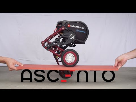
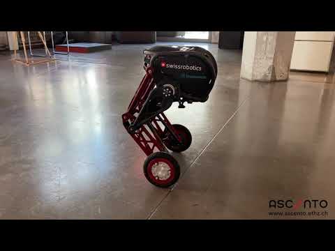
Ascento (Ascento 2) is the two-wheeled compact and agile jumping robot. It is associated with a high-quality engineering and science background. It combines the advantages of wheeled robot (moves quickly on flat terrain) and legged robot (overcomes obstacles):
A compact and agile jumping robot designed for mixed environments. The combination of wheels and legs allows it to move quickly on flat terrain and to overcome obstacles by jumping. Its small form factor renders it fit for tight indoor spaces and shows potential for high agile indoor mobility tasks.

The main parameters of the robot are:
- Total weight: 10.4 kg
- Operation time: 1.5 h
- Max. jumping height: 0.4 m
- Max. linear velocity: 8.0 km/h
- Max. angular velocity: 1.1 rad/s
- Control: 3D mouse and gesture control
- Cameras: Vision algorithms for autonomy
The robot is relatively light. To reduce mass and increase the strength of the leg structural parts it has been used topology optimization. Topology optimization is a numerical method that finds a geometry for given set of loads, design space, boundary conditions and a target mass with the goal of minimizing stresses within the structure. The shape of parts is complex therefore they were 3D printed out of PLA12 nylon using selective laser sintering (SLS) technology. Each leg can be extended and the system’s total height can be adjusted between 31 cm and 66 cm. The goal of the leg mechanism is to decouple stabilizing and jumping control as much as possible:
This was realized through a three bar linkage which approximates a linear motion of the wheels perpendicular to the ground. By making the line pass through the system’s center of mass the leg motion dictates a jump trajectory that does not cause a body rotation. As such a mechanism cannot achieve a perfectly straight line, the linkage is optimized numerically for six geometric design parameters with a mean squared error approach to the desired linear trajectory, whereby the optimal lengths and angles of the bars were obtained.
As the robot is in an equilibrium position while standing still, it uses hardly any energy to balance. The springs in its knees compensate its own bodyweight, so it needs most of its energy only to accelerate, jump and for the computer.

To jump high torques are needed. For this purpose ANYdrive series-elastic actuators were used, which allow peak torques of up to 40Nm and have built-in position and torque control. Maxon EC90 motors with a maximum torque of 3.5Nm are utilized in the custom wheel assembly hub motor. It provides smooth stabilization and to counteract disturbances, of the tilt angle of the mechatronic system, near-zero backlash and high wheel torques. All four motors communicate via a controller area network (CAN bus). A Controller Area Network (CAN bus) is a robust vehicle bus standard designed to allow microcontrollers and devices to communicate with each other's applications without a host computer. The system is also equipped with an inertial measurement unit (IMU) and a microcontroller to allow communication between the IMU and the computer. Ascento components and suppliers:
- Wheel Motor: Maxon EC90 Frameless
- Wheel Motor Motion Controller: Maxon EPOS4 Compact
- Hip Motor: ANYbotics ANYdrive
- Wheel Motor: USB-to-CAN ixxat USB-to-CAN V2
- Hip Motor USB-to-CAN: Lawicel CANUSB
- Motor Battery: Hacker LiPo 5000mAh 3S
- Computer Battery: Turnigy LiPo 2200mAh 4S
- Onboard Computer: Intel NUC KIT NUC7i7BNH
- Microcontroller: Arduino Uno
- IMU: Analog Devices ADIS16460
- Wheel Encoder: AEDL-5810-Z12
- ToF Distance Sensors: Terabee TeraRanger Multiflex
- 3D Mouse: 3Dconnexion SpaceMouse
- Gesture Control Device: Leap Motion Controller

All software is written using C++, because software must be computationally efficient to enable high bandwidth controllers. To apply model-based control strategies and advanced state estimation techniques a system model to describe the robot’s rigid body dynamics is derived.
In addition, the robot operating system (ROS) framework is used for high level communication. A Kalman filter is implemented using sensor data obtained by the IMU and motor encoder measurements. In combination with the model knowledge from III-C, the Kalman filter provides an estimate of the system’s state dependent on the hip motor position as described in IV-A. The estimated state information is fed to the controller together with the desired pose from the user.
See the Ascento in action (autoplay playlist):
The activation of the jump controller triggers a predefined jump sequence, which includes:
- retract legs,
- trigger jump,
- extract legs,
- fly phase,
- land.
It overrides the current drive controllers and takes full control of the robot. The jump controller is a heuristic feed-forward controller, inspired by human jumping motion. The Ascento robot has also fall recovery control system, so in case of any troubles, it will stand up by itself. A jump controller and a fall recovery controller are implemented separately.
References:
Klemm V., Morra A., Salzmann C., Tschopp F., Bodie K., Gulich L., Küng N., Mannhart D., Pfister C., Vierneisel M., Weber F., Deuber R., Siegwart R.: Ascento: A Two-Wheeled Jumping Robot, Conference paper, International Conference on Robotics and Automation ICRA, 2019.
Klemm V., Morra A., Gulich L., Mannhart D., Rohr D., Kamel M., Viragh Y., Siegwart R.: LQR-Assisted Whole-Body Control of a Wheeled Bipedal Robot with Kinematic Loops, Conference paper, International Conference on Robotics and Automation ICRA, 2020
Comments